Pressure regulators are vital in many industries as part of a gas or fluid delivery line or system. Often, device manufacturers gear their products to specific industries by following design standards and guidelines for safety, cleanliness, leak integrity and connection interface. Therefore, finding trusted brands that cater to the industry for your application should be the first step in your search. The next step is to fit a regulator for your application. Manufacturers typically have an assortment of regulator product offerings ranging in size; however, selecting the right one can take time and effort.
Choosing the right regulator can have critical positive consequences:
- A more efficient system
- Improved performance
- Reduced troubleshooting
- Reduced safety hazards
This post will help simplify your selection process by covering what factors to consider for your application.
What factors should you consider when selecting a regulator?
Pressure regulators are devices designed to maintain and control gas or fluid pressure. The ideal regulator for your system depends on your process and system requirements. Here are the key factors to consider when selecting a regulator:
- Inlet and outlet pressure
- Flow requirements
- System temperature
- System media
- End connections
- Tied vs. non-tied diaphragm
Inlet and outlet pressure
Knowing the upstream and downstream pressure requirements of your line or system sets the pressure envelope, narrowing down the field of regulators to choose from. Ensure you know the application’s operating pressure range and maximum pressure for both the inlet and outlet.
Key considerations:
- Is your inlet pressure stable, or does it fluctuate?
- Typically, source regulators connected to a gas cylinder will see a range of inlet pressures. As the cylinder depletes, inlet pressure to the regulator reduces. In contrast, regulators downstream (I.e., part of a distribution line being fed by a source regulator) will hardly have any fluctuation in inlet pressure.
- Supply Pressure Effect (SPE) – the regulator’s outlet pressure has an inverse response to the inlet pressure applied. SPE occurs due to the internal force balance happening in the regulator. It is measured as a rate of change in outlet pressure per every 100 psi change in inlet pressure. The change between inlet and outlet pressure is inversed. For example, if the SPE of the regulator is rated at 1.5psi/100psi, the outlet pressure will increase by a rate of 1.5 psi per 100 psi decrease of inlet pressure and vice versa. Typically, the manufacturer will publish SPE values. Because systems with a maximum pressure limit are sensitive to SPE, it is common to have a pressure relief valve installed in-line to limit maximum pressure. Another method to counter-act SPE is to add another pressure regulator in-line after the source regulator (or use a two stage-regulator). In this case, the source regulator’s outlet becomes an intermediary to ballast the pressure feeding the downstream regulator, reducing the effect of SPE downstream.
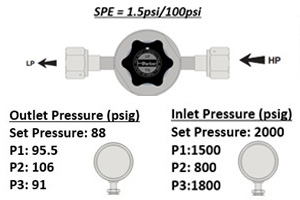
Figure 1 – Example of supply pressure effect on inlet and outlet pressure.
Outlet Pressure – The outlet pressure range of a regulator is determined by the range spring. A lower outlet pressure range would have a “lighter” spring, while a higher outlet pressure range would have a “heavier” spring.
Sensitivity – The amount of spring force produced by the range spring directly correlates to flow performance and adjustment resolution of outlet pressure. Lighter springs generally produce less pressure drop at flow and provide a finer resolution of pressure adjustment. Therefore, sizing a regulator for an application is critical to achieving optimal performance. Selecting a regulator tailored to the application by rounding up the outlet pressure target to the nearest outlet range option is ideal for proper sizing. Systems can also have varying operating pressures when being fed by multiple regulators. Especially if the range of varying operating pressures is wide, it is inadvisable to go with a “one-size fits all” selection approach. High-outlet pressure ranges may not be suitable for low-pressure applications due to the level of sensitivity. It may not allow the precise adjustability needed to reach a target outlet pressure. In addition, a high-pressure regulator in a low-pressure application will experience a greater amount of pressure drop at flow.
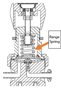
Figure 2 – The knob drives the range spring, controlling outlet pressure.
Flow requirements
The flow rate of your system requirements affects the size of regulators you need.
Key considerations:
- It is best practice to verify the inlet, outlet and flow parameters with flow curves.
- Is the flow rate constant or variable? Knowing the flow schematic of the system that a regulator is feeding is important for sizing. Regulators feeding downstream can feed a single line or branch to multiple lines. With branching lines, it is good to know the operating flow range and the peak downstream flow to ensure the regulator has the available capacity to support all conditions. You can estimate downstream flow demand by totaling the flow capacity (Cv) of all downstream valves that would flow simultaneously in typical and maximum conditions.
- With those flow values established, you should reference a flow curve to ensure the flow demand is within the operating range of the regulator and that the outlet pressure drop is within an acceptable limit.
- Flow options – Manufacturers often provide multiple flow options within a product series to optimize applications that demand different flow levels.
- The published Cv of a regulator should be taken as a point of reference for selection and can work for a relative comparison. It is not indicative of a regulator’s flow performance. Unlike valves, regulators do not operate in a fully open state. In some cases, manufacturers will indicate the flow range of the product series. However, checking conditions against a flow curve is always recommended to verify if the device’s optimal flow range supports the application. Typically, the manufacturer will provide flow curves at common parameter settings. You can often extrapolate a flow curve between what is published. In addition, manufacturer flow curves are typically produced with N2 at room temperature. Be sure to take gas and temperature correction into account for your application.
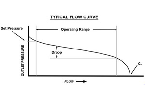
Figure 3 – Example of a typical pressure-reducing regulator flow curve.
Set Pressure / Set Flow: Initial regulator outlet conditions
Drop (Droop): Decrease in Outlet Pressure with increasing Flow
Cv: Flow capacity at wide open position
Operating Range: Optimal flow range, linear portion of the curve
System temperature
Processes can reach extremes in temperatures, especially due to changes in pressure. Your choice of regulators must withstand the ranges of temperatures that occur in typical operating conditions. System temperature and media determine the most suitable seal material option for your application. If the system operating temperature exceeds the limit of seal materials ratings, it can cause leaks internally and/or externally, which create safety hazards and significant downtimes.
System media
The type of system media (gas, liquid, or steam) along with temperature will affect the longevity of the regulator you select. Surface treatments such as electropolish and passivation, in addition, to surface finish, can enhance corrosion resistance and cleanliness with stainless steel regulators. Another consideration is seal materials. Metal regulators are especially affected since they are typically designed with plastic or rubber seals. Knowing media compatibility will influence the decision on the best seal material choice. Media that is not compatible can cause faster deterioration and decrease the life cycle, making the material compatibility between your regulator and your system media a key consideration.
End connections
End connection types are usually synonymous with the industry served and the means to provide the level of leak integrity needed. For example, ultra-high purity regulators used for semiconductor processes commonly have welded face-seal or tube-end connections due to more stringent leak rates. On the other hand, regulators for oil and gas industries commonly use National Pipe Thread Tapered (NPT) connections.
Tied vs. non-tied diaphragm
Tied diaphragm regulators physically connect the poppet to the diaphragm, resulting in a mechanically assisted positive shut-off acting as a safety shut-off feature in the event there is leakage across the seal. Tied diaphragms allow the spring to be removed from the wetted area, making the operation far cleaner and reducing particles that could be generated during operations. Therefore, tied diaphragms are preferred in ultra-high purity (UHP) applications. In applications with hazardous and corrosive media, tied diaphragms are considered an added safety feature. However, a tied diaphragm costs more due to the increased number of components.
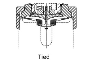
Figure 4 – Regulator cross-sections showing the absence of the poppet spring in tied diaphragm design, which minimizes components in the wetted flow path.
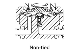
Figure 5 – Regulator cross-sections showing the non-tied tied diaphragm design
Other factors to consider
- Material of construction
- Cleanliness
- Leak rate
- Sensitivity of regulator
- Flow curve
Conclusion
No matter what your application is, choosing the proper regulator is vital. Your regulator supplier can help with the selection process by providing pressure and flow requirements, sizing information, temperature ranges, and other essential information.
Key Takeaways:
- A single regulator may only address some of your system requirements.
- If your applications require regulators with a wide range of flows, a single high-flow regulator type will need to be more sensitive to handle your low-flow applications.
- Flow curves are a valuable resource to ensure that your regulator will match your application for performance optimization and process optimization.
- A regulator is not a shut-off device. Instead, a valve should be paired with the regulator for a proper shut-off.
The better you understand your application’s requirements, the more equipped you will be to make the right decision on a pressure-reducing regulator. Your supplier can provide you with key specifications, such as pressure and flow requirements, temperature ranges, and sizing for your system needs.
More Articles