Flowmeter technologies
The pie chart of Figure 1 indicates the variety of flowmeter technologies available and their representation in the processing industries. Many of the tehnologies shown–electromagnetic, vortex, turbine, ultrasonic, and anemometer–actually measure the flow velocity of the fluid in the pipe. Multiplying the measured average velocity by the cross-sectional area of the meter or pipe results in volumetric flow rates. Flowmeters based on differential pressure–orifice plates, nozzles, wedges, Venturi’s, and pitot tubes– introduce a restriction in the flow. The unrecoverable pressure loss caused by the restriction is a measure of the volumetric flow rate.
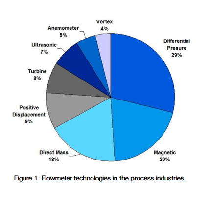
If the application requires a measure of the mass flow rate, volumetric flowmeters must be supplemented with additional information, such as fluid density, pressure, and/or temperature. Some multivariable flowmeters and transmitters incorporate an additional sensor to provide this information. On the other hand, Coriolis flowmeters (and thermal probes for gas) directly measure mass flow rate. Currently at 18% of the market, they are steadily increasing market share.
Figure 2 shows the applicability of certain flowmeter technologies to various liquid and gas conditions. Green indicates the technology will generally work while red rules it out. Yellow indicates that the flowmeter technology will sometimes work if certain conditions are met. Obviously more than one technology can apply for a given set of fluid conditions. These are the cases when basing the selection on minimizing energy can further narrow the choices.
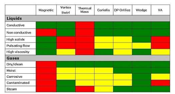
Figure2. The selection of flowmeter technologies depends on the application.
Red, no. Green, yes. Yellow, maybe.
Why minimise energy?
Many flowmeter technologies introduce pressure loss into a system. Pressure losses equate to energy losses and costs. Valves, pipe friction, reducers, expanders, and measuring devices such as flowmeters all increase the Permanent Pressure Loss (PPL) in the system. Some flowmeters require upstream reducers and downstream expanders to operate properly.
For new processes, engineers often consider PPL when designing a system because it’s important in sizing the pump (liquids), compressor (gases), or boiler (steam) to meet process conditions and to deliver the desired pressure and/or flow. For operating processes, PPL leads directly to the need for compensating energy, which can equate to significant increased annual operating costs. By minimizing pressure losses in a process, engineers can cut the need for top-up pumping or compression as well as environmental impact. In the case of steam boilers, which are expensive, the ability to retrofit existing flowmeters with those having low pressure losses can boost the effective boiler capacity.
By selecting flowmeters with low pressure losses, engineers can:
– Reduce pumping/compressing cost
– Increase capacity
– Minimise compressor, pump or boiler size.
The amount of pressure lost in a flowmeter depends on three factors: the fluid density, the square of the fluid velocity (Vf)2, and the degree of obstruction to fluid flow, (Kmeter). The following list roughly ranks the magnitude of the Kmeter factor for various flowmeters, from greatest pressure loss to lowest.
- Coriolis

- Orifice/Nozzle
- Turbine
- Vortex
- Venturi
- Averaging Pitot tube
- Electromagnetic/ Ultrasonic (negligible PPL)
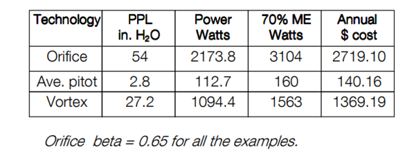
Replacing an orifice plate with an averaging pitot tube, for example, can reduce the permanent pressure loss (energy requirement) by a factor of 20. Averaging pitot tubes offer minimal irrecoverable pressure losses as well as being inexpensive and simple to install.
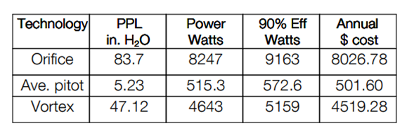
Examples of energy usage
Calculation of energy usage per unit of time depends on the product of the permanent pressure loss (PPL) and the volumeteric flow rate Q divided by the mechanical efficiency (ME) of the system in decimal.
Incorporating units of measurement–make-up power in watts, PPL in inches of water, and Q in CFM–the equation becomes:
Power = (0.118 PPL * Q) / ME
The system mechanical efficiency ME is the product of the decimal efficiencies of the electric motor and that of the pump or compressor. Boilers also have an associated system efficiency. The following analyses assume a system efficiency of 0.70 for nitrogen and water and 0.90 for the boiler. Lower system efficiencies obviously require more power to make up for the pressure losses in the process.
The annual cost can then be calculated by multiplying the energy by the local electricity cost ($/kwh) and the number of operating hours in a year (8,760 total hours per year). The examples below assume a cost/kilowatthour of $0.10, which is close to the national average (in 2010). Electric rates, however, differ by state and by residential, commercial, and industrial end uses. They can range from 6 cents to 25 cents per kwh.
Nitrogen, water, and steam serve as representative gases and liquids for a great many materials common to chemical plants. Below are calculations of the savings possible for an orifice, averaging pitot, vortex, and magmeter (liquids only) flowmeters using these fluids as examples.
Example1. Nitrogen gas
– 4-inch line
– Normal flow: 1500 SCFM
– Pressure: 50 psig
– Flow at 50 psig (64.7 psia)= 1500 / [64.7 / 14.7] = 341 CFM
– ME: 70 percent
– 4-inch line
– Average flow: 26.74 CFM
– ME: 70 percent