Achieving a differential pressure measurement requires two key elements – a primary element, which creates a restriction or reduction in the flowline to cause a pressure drop – and a differential pressure transmitter to calculate the flow.
Selecting the right differential pressure flowmeter requires an understanding of the key factors that can affect their suitability for specific types of applications, including:
Calculating the differential pressure
The relationship between velocity and differential pressure provides the basis on which all differential pressure devices operate.
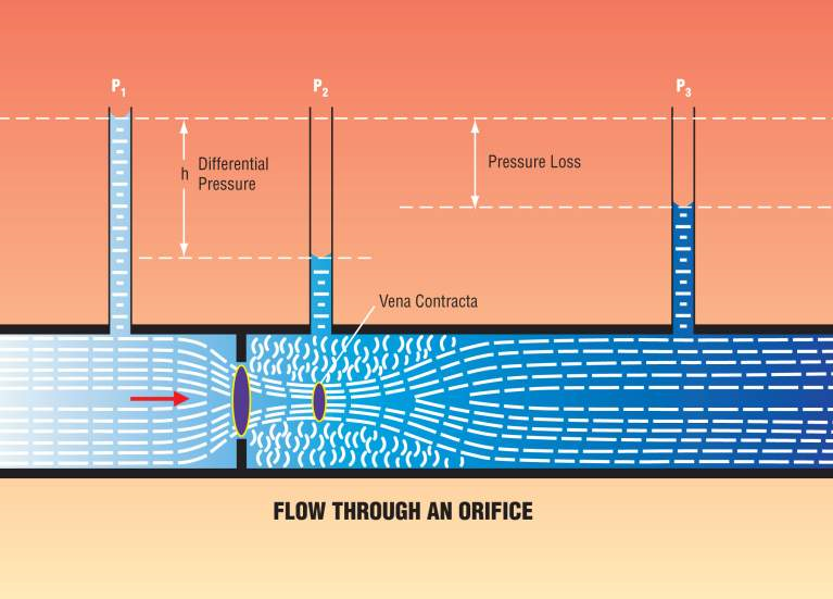
When the measured fluid flows at a velocity through the restriction, the area of the fluid path is reduced, causing the fluid to move at a higher velocity to maintain the same flowrate.
As the velocity increases, the kinetic energy also increases, causing a consequent reduction in the pressure energy. This creates a lower pressure in the meter throat compared to that upstream of the throat.
Each DP device deviates to some extent from the calculated relationship, which is based on the ratio of restriction diameter to pipe diameter. One reason is that when the fluid passes through the restriction, it continues to ‘converge’ for a short distance. This means that the minimum diameter of the fluid “jet” (called the vena contracta) can be smaller than the throat of the restriction and the velocity in it is therefore higher, as shown in the following diagram.

Consequently, the actual pressure reduction is greater than that calculated from the restriction diameter. To correct for this, a Coefficient of Discharge is applied. The ideal value of this coefficient would be 1.0 but the actual value varies from one class of DP device to another. It also varies within a given class of device, depending on the b-ratio (the ratio of the restriction diameter to the pipe bore diameter).
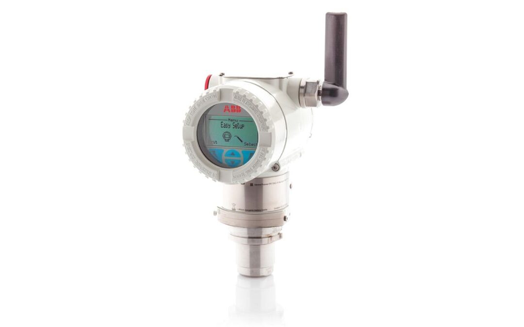
When using the meter to measure flowrate, it is necessary to know the differential pressure generated, which is usually achieved using a differential pressure transmitter.
Know your Reynolds Number
Reynolds Numbers are a means of comparing the dynamics of two or more flow systems which are geometrically similar but dimensionally different. To select the appropriate flowmeter, it is necessary to calculate the Reynolds numbers of the application. These are the ratio of momentum against viscosity and can be obtained by calculating the minimum and maximum fluid flow and viscosity figures of the application.
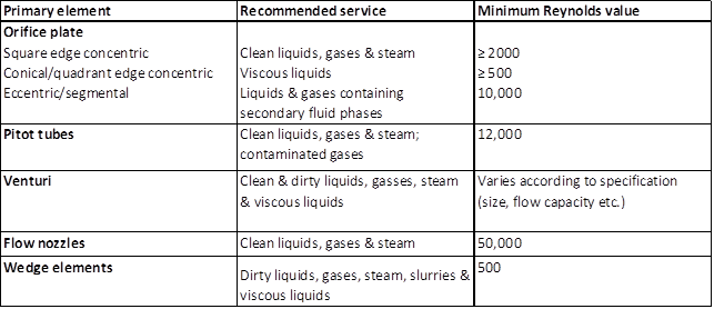
A general guide for matching DP flowmeter selection to Reynolds Numbers is outlined below:

Reynolds Numbers allow a common fluid such as water to be used as the calibration medium both for liquids and gases. Gases, however, have very low viscosities and tend to be transferred at high pipeline velocities. As can be quickly deduced from the Reynolds Number formula, this leads to very high Reynolds Numbers being generated, much higher than those normally achievable using water as the calibrating medium.
This often creates the requirement for the calibration medium to be in the same “phase” as the application to better establish its stability under close-to-operating conditions. These factors together lead to some devices being calibrated using gas, a complex and costly operation often requiring the use of specialist third party gas calibration centres.
If a water calibration is acceptable, some manufacturers, ABB included, have suitable water calibration rigs in-house, enabling them to offer economic flow calibrations.
For more information on the ABB – Flowmeters, contact us using the form below.


